| THE INDUSTRIAL RAILWAY RECORD |
© DECEMBER 1967 |
AN INDUSTRIAL MONORAIL
SYDNEY A. LELEUX
Civil engineering sites are rough places. Materials have to be carried about and dumpers, or even men and wheelbarrows, soon churn up the ground, adding to the difficulties. To overcome this transportation problem Road Machines (Drayton) Ltd., of Horton Parade, West Drayton, Middlesex, designed a simple monorail system. The first Mono-Rail Transporter was sold in 1949 and since then many have gone for use in all parts of the world. It is patented in 48 countries, spread over all five continents.
The rail is 9in high. The running surface is 1Ľin steel rod supported by steel plates 21Ľin long, 6Ľin high, tapered from 1in thickness at the top, to 2˝in at the bottom. These plates, four to a 12ft length, are mounted on inverted 1˝in by 3in channel forming the base of the rail. In the spaces between the supporting plates are square plates, each with a hole in its centre for attaching auto stops or buffers. The rail is made in 12ft and 6ft straight lengths and 6ft curves, of 12ft radius, twelve pieces to the circle. These lengths are nominal; for example a 12ft straight is 11ft 8in long, the other 4in being a short length incorporated in the rail stands. A 12ft straight weighs about 1˝cwt. Special lengths are supplied to order.
Recently a new design of rail has been introduced, of box section. Steel plates, 8˝in high and ⅛in thick are welded to the flanges of 2ľin by 1in channel. Along a line 1˝in above their lower edge the plates are bent inwards until their outer faces are 1Ľin apart. The lower section of the 1Ľin rod is made for fastening train stops by boring pairs of holes in the side plates at 3ft centres. A piece of tube is then welded across the gap between each pair of holes.
The rails are supported and joined by stands. These are supplied in four sizes. The standard size – an "H" frame – is a 17˝in by 1˝in by 3in "I" girder between the 2˝in outside diameter tubes which form the upright. Each tube is 7˝in high with five holes bored in it at 1˝in centres for a pin. Inside each tube is a 9in length of 2in outside diameter tube, with seven holes at 1Ľin centres bored in it and having a 3˝in diameter foot at its lower end. The two sets of holes allow the stand to be adjusted easily, to overcome irregularities in the ground. The rail height above the ground can be between 1ft 2˝in and 1ft 10in with a standard stand. The figures for the other sizes are 2ft to 3ft, 3ft 5in to 5ft 4in, and 5ft 7in to 7ft 8in. These larger stands have splayed legs, braced for rigidity, with adjustable sections at their feet. A variation of the standard type has "U" shaped feet so that the monorail can be laid on scaffolding.
Mounted on the "I" girder is a short length of rail. At each end of the channel base is a peg which fits into a hole at the end of the rail section. The ends of the rod forming the top of the rail are bent down to form a peg which mates with a hole in a strip of steel mounted below the running rail on the stand. Thus a simple joint is made without using nuts and bolts. A simple catch prevents the rail accidentally jumping out of its support.
Points are available, being two "H" frames, one 17˝in wide and the other 30in, spaced 8ft apart by two 2˝in tubes. The wider frame has two "rail joiners" mounted on it 15in apart. The point blade is pivoted at the narrow end and rests in either position, held by the usual method. A foot pedal is provided to lift the blade out of its lugs, but it is moved across by hand. In some locations, the track is broken and a straight or curved section inserted as needed.
The two types of vehicle used on the monorail are power wagons, and trailers, the latter being identical in construction and size to the former, but without engines. Vehicles are coupled by a short steel bar, forked at each end. Each fork fits over a plate on the wagon frame and is secured by a pin. The wagon consists of two 19in square frames of 3in by 1˝in channel joined by 6ft 6in of 3in by 3in angle to give an overall length of 8ft 3in. The joints are strengthened by steel plates bolted over them. The frame clears the rail by 1Ľin.
At the centre of each side of the square end frames is a roller which engages a circular girder of 3in by 1Ľin channel. This circular frame carries the wheel and power unit, and its construction permits the sharp curves to be taken easily. The carrying wheel is 10in outside diameter, with a 1in deep flange. A short distance in front of each carrying wheel is a pair of 2in diameter horizontal wheels. These bear on the side of the head of the rail, so guiding the main wheel. The wagon is kept stable by a pair of 4in diameter wheels, 1ľin deep, bearing on the sides of the channel base of the rail. These wheels are carried on brackets fastened to the circular frame.
Power is supplied by a 412cc, 7˝hp air−cooled four-stroke petrol engine, mounted over one wheel. Transmission is mechanical on the Mark 1 power wagon and hydraulic on the Mark 2; the latter has both wheels driven. Hydraulic lines are fastened to the sides of the frame to convey the power to the other end of the wagon. Fully loaded power wagons can surmount a gradient of 1 in 12 (Mark 1) or 1 in 9 (Mark 2) alone; with one trailer 1 in 18 can be climbed, and with two trailers 1 in 28 (Mark 2). Speed on the level is 100 yards per minute (about 3˝mph). The forward and reverse controls, and the brake levers are duplicated. The latter are extended downwards to engage with trips bolted to the centre of the rail for auto control. Due to the auto stops no drivers are needed but, if it is desired to have one, a seat can be fitted behind the engine. Brakes are a friction shoe on the Mark 1 and double-shoe external-contracting type incorporated in the hydraulic system in the Mark 2. Non-powered wheels are covered by steel sheeting in the form of a truncated pyramid. A few electrically driven wagons have been made for situations where petrol engines cannot be used.
The usual body is a side tipping skip of 12˝ cubic feet capacity (27 cubic feet heaped), which is equivalent to a payload of 1,800lbs. The skip is 4ft wide (4ft 2ľin over the 1˝in wide lip), 4ft 6in long (4ft 8in over lip) and 18˝in deep. The earliest skips were 4ft long, with vertical ends, but now they are made with ends 4ft apart that are vertical for the first 12in and then slope outwards to 4ft 6in. There are other types of body available. One type gives side or bottom discharge for shuttering work and is fitted with lugs at each corner for lifting by crane. For narrow column work three smaller skips nest side by side in the standard skip. Each smaller skip has a handle, pivoted near the bottom apex, so that the skip can be picked up by crane and a simple "U" catch allows it to be tipped. Some bulb growers at Spalding have boarded over the well of the wagon frame and fitted a platform supported by legs at each corner to carry boxes of bulbs. Monorails have been used in forestry with body removed and bolsters with stanchions fitted at each end. Yet another type is a cradle for carrying pipes. On building sites the track is quickly and easily laid. Two men can lay 100 yards in half-an-hour over average ground. As it is supported only at intervals, excavations, streams, ditches, boggy ground, etc., are no hindrance, enabling the line to be laid in the most direct route. After four lengths have been laid, further rail can be brought up on the monorail. An ingenious trolley is used to carry the wagons to the site. Basically, this is a length of rail with a pair of wheels and a handle at one end. The trolley is wheeled to the end of the track, the rail fastened by the usual system of pins to the main line and the wagon run off under its own power.
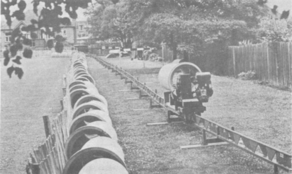
Monorail carrying 3ft diameter pipes. Rail is of early pattern.
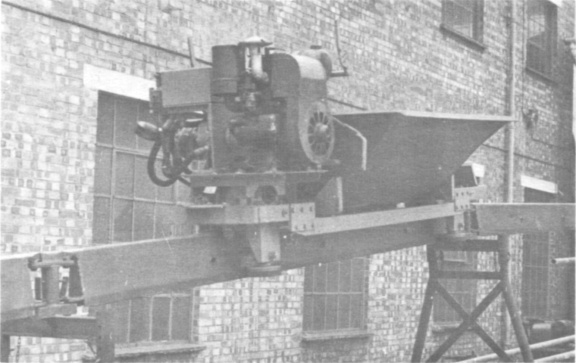
Mark 1 Power Wagon running on later type rail.
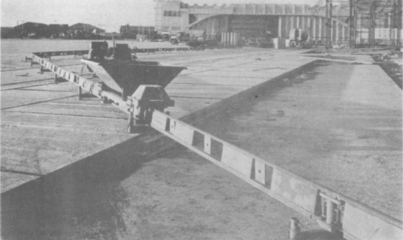
Mark 2 Power Wagon on box type track. (Road Machines (Drayton) Ltd.)
When the monorail is being used to carry concrete, for example, the train is dispatched by the mixer operator and runs unattended to an autostop fitted at the point where the placing gang is working. A single power wagon operating over 100 yards of track takes the same time for a complete cycle as a standard 18/12 concrete mixer – three minutes – and has an output of 9 cubic yards per hour. Two trains of a power wagon and trailer can take the output of a pair of 18/12 mixers and carry it 200 yards, a loop being provided half way. At the tipping site the track may just finish, and be continuously shortened as the work progresses. Alternatively, if the site is wide, the line may run up the edge and then curve across the works. As this involves relaying several sections of rail every time the line is shortened, the manufacturers have designed a bridge. Standard track is laid up each side of the placing site. The bridge of simple braced tubular construction is carried by a wheel in each corner which runs on the side tracks. A semicircle of track is laid across the bridge – which comes in spans of 24ft, 30ft, and 36ft - and at the ends there are specially designed rails which fit over the side rails, forming a ramp up on to the bridge track. The whole structure can be pushed to any point by two men and so no rails have to be relayed as the work proceeds.
The Western region of British railways has used this type of monorail for viaduct repairs when the simple track was laid in the cess beside the main line, and also when widening a cutting at Plymouth ("Railway Gazette", 4th April 1958). In the latter case the monorail was laid on a ledge cut into the base of the cutting and the line continued to a dead end siding where it was laid on sleepers placed across the wagons for removing spoil. A dumper could never have been used on such a site.
In addition to use on building sites some permanent monorail lines have been laid. On these the track is often bolted to brick or concrete pillars which replace the "H" frames. The writer knows of two monorails in small brickworks carrying clay (at Blockley, and at Knowle, Gloucestershire), in sewage farms (at Wollaston, and Roade, Northamptonshire, and at Andover) and at J. T. White & Sons’ bulb farm, Spalding ("The Grower", 13th February 1960). There are no doubt others scattered over the country. A further example of the system’s versatility is a line carrying fish at a port in Finland, and another in Sarawak, about a mile long, being used to construct a water pipe line. The latter will be retained for maintenance purposes.
One advantage of the monorail at sewage farms is that the line can be laid down the centre of the sludge beds and is always ready. With conventional railways temporary track has to be laid into each bed when it is ready for loading. At Spalding, the manager of the farm estimates that the monorail (500 yards of track, with four men) replaces ten men and six tractors, and has the added advantage of not churning up the ground.
I hope it can be seen from this article that Road Machines (Drayton) Ltd., have, in their Mono-Rail, provided a useful solution to the problems encountered by contractors. I am indebted to Mr Waplington, Publicity Manager, who has been of great help to me in the preparation of this article.
![]()
![]()
![]()
![]()
![]()