| THE INDUSTRIAL RAILWAY RECORD |
© SEPTEMBER 1967 |
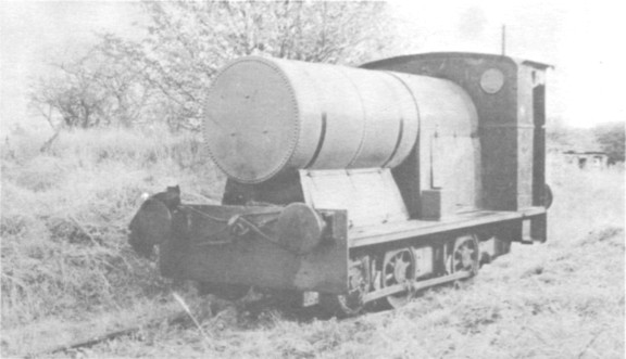
BAGULEY 800
RODNEY WEAVER
(Photograph by the Author)
In March 1920 Dought Son & Richardson placed an order with McEwan Pratt & Co Ltd for a 100 hp internal combustion locomotive capable of negotiating 75ft radius curves and 1 in 40 gradients. Of course, McEwan Pratt & Co was a pseudonym for Baguley Cars Ltd of Burton-on-Trent where this locomotive was built under works number 800. The delivery date quoted was October 1920, but in fact it was only just at the frame stage by then and in the event was never delivered to the original purchasers.
A lot of thinking went into the design of this locomotive, the intention being to make it virtually indestructible. In terms of power it was the largest petrol locomotive so far built by Baguley, although larger railcars had been made and a 150
hp 0−4−0 petrol hydraulic laid down several years earlier; this last was not completed and the frames were used for Baguley's only standard gauge steam locomotive, works number 621 (officially 2001). No.800 was left on the builder's hands until 1933, fulfilling the virtual sinecure of works shunter. It was painted white in its early days and must have been a most impressive piece of publicity material. Eventually it was sold to a forerunner of the London Brick Company and went to the King's Dike Works at Whittlesey, where it worked until about 1950, being then transferred to the nearby Gildenburgh Works for the remaining fifteen years of its active life. A mechanical failure almost coincident with the "rationalisation" of local main-line freight services (British Railways closed the Works sidings made it redundant in late 1965 and at the time of writing, it awaits a decision on its future. I hope that this example of an early internal combustion locomotive will be preserved as it is in virtually original condition and an excellent example of a McEwan Pratt/Baguley product.
Perhaps part of the prejudice against internal combustion locomotives is because their salient features are less readily apparent than with steam power. Certainly there is nothing cheap about this design, which was, like most Baguley products, regarded as an alternative to steam and not a substitute. The general appearance is of a mock-steam locomotive, which has been exploited by Baguley in their miniature locomotives ever since. In fact the layout is quite logical, with the engine adjacent to the cab and the water tank mounted over the lowest part of the transmission. The use of tank cooling may seem strange now, but it was common practice not many years ago – indeed, a modern Simplex was converted from radiator cooling about a year ago. The frames are very much the same as for a steam locomotive, if anything a little stronger than most, made from deep one-inch plate with several cross members. Additional strength is derived from the six-inch girders which form the engine and gearbox sub-frame. Driving wheels are 2ft 6in diameter on a wheelbase of 5ft 6in.
The engine is immediately ahead of the cab. It is a Baguley design with four bin by 8in cylinders (about 16 litres) developing 100 bhp at about 1,000 rpm. This mighty engine with its forced feed lubrication drives an appropriately massive transmission, which is shown in diagrammatic form in the drawing. It is a development of the double cone clutch system, first used on Baguley 774, with one difference: there is a separate gear box on 800 whereas the smaller types had coaxial bevel reverse gears combining both functions. Operation is by the larger of two control levers in the cab. This operates a linkage which incorporates a spring to apply load to the clutch, hence the notches in the quadrant. This linkage moves a sleeve on the drive-shaft which in turn works the lower ends of three levers marked F on the diagram. These are connected to both the clutch case E and the inner driving plate D, the case being free to slide axially and the inner plate free to move axially within the case. Movement of the levers therefore traps one or other of the driven plates between the case and the driving plate, exerting considerable clamping pressure in the process. The driven plates are attached to coaxial shafts which carry the pinions inside the two-speed constant-mesh gearbox. The output shaft from this drives a pair of bevels on a cross shaft, one or other of which is engaged by a dog clutch according to the direction of motion. This shaft carries pinions at each end which engage with a gear ring bolted to each flycrank, at which stage the drive "comes into the open" to the uninitiated observer.
As already stated, the cooling water, some 500 gallons of it, is carried in the large tank. This has no filler although one was designed for the purpose – the large hole in this tank is the only "cheap" feature of the whole machine. Petrol is carried in a tank above the engine, and oil in a transverse tank below the sump itself. The cab layout is simple, but a lot of physical effort is involved in driving. From left to right, the first item is a lever on the floor attached to a cross-shaft which locks the starting gears, behind the central cover, out of engagement when running. Next, on the bulkhead, are the contact breaker and tell-tale for the lubrication system. Behind the cover, immediately below the central line of rivets, is the decompression lever, of which more anon; then come the reverse (short) and gear change (long) levers with the ignition advance/retard control just beyond. Behind the hand brake is the sanding lever and lastly there is the throttle. The layout has changed somewhat over the years, but this was the original.
To start the engine the carburettor is flooded and some petrol poured into each cylinder through priming cocks; the decompression lever is pushed forward and the starting gear moved into engagement by the lever already noted. Two starting handles are used, one on each end of a transverse shaft running above the cab (just above the square opening), and the engine swung over. (I am told that it usually went first time and that it was possible to turn it single handed). As soon as it is running, the starting gear is locked back and the decompression lever pulled back. To move off, the direction of travel is first selected and the clutch lever pushed forward to take up the drive in low gear. To change into high gear the clutch lever is pulled back. Anyone who thinks that no effort is involved should try the 4ft 6in tall clutch lever!
Unfortunately, no copy of the maker's specification has yet been found, so no more detailed information can be given of performance. Our drawings are based on a Baguley original general arrangement, but incorporate such variations as are obviously original. The present condition is not very different anyway.
I would like to thank Mr W.R. Souster of E.E. Baguley Ltd for his generous assistance, particularly for the loan of original material, and also the members of the LBC staff at Whittlesey who have been so helpful during my enquiries.
(The writer who already owns a 2ft gauge 0
−4−0 petrol locomotive – Baguley 774 of 1919 – is hoping that it will be possible to preserve also the subject of this article. He states that the locomotive is in quite good condition with little corrosion, and although the platework is battered in places it could be restored easily. In his opinion Baguley 800 is worthy of preservation because it is a good example of a relatively early internal combustion locomotive still in original condition. No such machine exists in any museum as yet, although Britain produced the first internal combustion locomotive in 1896 (built by Richard Hornsby & Sons of Grantham, incorporating the Hornsby Akroyd oil engine and led the World in design for almost two decades until the experiments of Professor G.V. Lomonossof in 1918-1920. Readers who would like to contribute to this cause should contact the writer at: 4, Queens Close, KENILWORTH, WARWICKSHIRE. – Hon. Eds.)
![]()
![]()
![]()
![]()
![]()