| THE INDUSTRIAL RAILWAY RECORD |
© APRIL 1974 |
HANDYSIDE LOCOMOTIVES
TREVOR J. LODGE
"That to every existing locomotive may easily be adapted an apparatus which, without clashing with any existing arrangement, shall enable the locomotive to become, anywhere and at any time, a stationary hauling engine, enabling it to use the whole of its boiler power as tractive power on carrying weight, not having to drag its own weight as well, and this tractive force no longer dependent on the adhesive force of the wheels on the rails. And further ... the tractive force can be almost indefinitely increased by means of suitable gearing, with a proportionate decrease in speed, to the hauling of an immensely greater tractive resistance than is ever exerted by a locomotive under ordinary circumstances."
This is what "Iron" had to say in their issue dated 17th October 1874 about the theory underlying Handyside's Steep Gradient Apparatus. Considering the widespread coverage accorded to Handyside locomotives following their introduction, frustratingly little seems to be known of the exact identities and later histories of the few engines equipped with this "Steep Gradient Apparatus". Henry Handyside, the patentee of the equipment, was one time Assistant Provincial Engineer to the Government of Nelson province in New Zealand. His invention was essentially no more than yet another Victorian attempt to extend the range of terrain over which it was possible to build and operate railways. Most attempts in this field inevitably involved the adoption of some form of rack rail, stationary engine or similar, but Handyside's "Steep Gradient Apparatus" was a brave try aimed at enlarging the sphere of adhesion worked railways. By use of the device inclines graded between 1 in 20 and 1 in 10 could be successfully surmounted without the need for a stationary engine or track modifications, albeit at an overall speed of little more than a snail's pace!
Briefly, the system involved using a locomotive alternatively as a mobile and a fixed haulage unit. It was coupled to its train by a steel wire rope wound round a drum mounted between the main frames of the locomotive and usually placed beneath the footplate. The drum was fixed horizontally in bearings located in the main frames and was driven either directly, or through gearing, by means of an auxiliary pair of steam cylinders fitted to the locomotive. Originally it was proposed to use a steel chain on the haulage drum but, in the event, all the well‑documented examples were supplied with a wire rope instead. In addition to this winding equipment the locomotive was provided with gripping strutts (one on each side): similar strutts were fitted on to carriages or wagons of the train being hauled. By lowering the gripping strutts on to the running rails the driver (or guard) could hold the locomotive (or rolling stock) stationary. These braking strutts actually gripped the sides of the rail, thus preventing damage to the rail table (top surface). They were made in three principal sections, namely a centre piece and two side pieces hinged to it. During use the centre piece was brought into contact with the table of the running rail and the side pieces fell over the rail edges. As downward pressure was applied on the braking strutt the centre piece of the strutt acted as a fulcrum, forcing the side pieces to grip the rail edges tightly. Reference to the section drawing of the strutt and its positioning on the drawing of the early Handyside proposed locomotive conversion will serve to explain its working more clearly. Any undesired backward movement of the loco caused greater downward pressure on the strutt and this in turn gripped the sides of the rail more tightly, thus arresting the movement. If the gripping strutt was inadvertently left in position then forward movement of the locomotive (or wagons) so fitted tended to force the strutt away from the rail, into the "off" position.
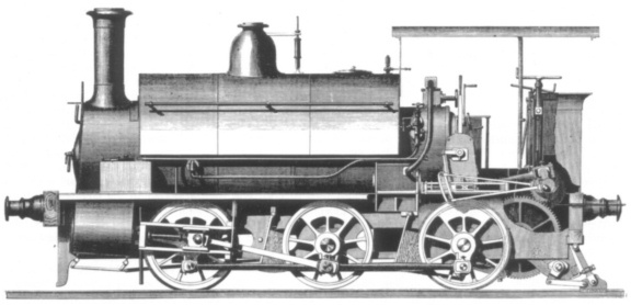
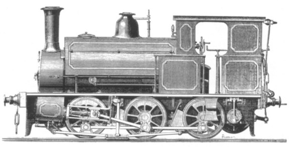
The proposed Handyside 2‑4‑0 locomotive which appeared in "The Engineer" on 11th September 1874.
When hauling a train on easily graded track the coupling wire rope was kept wound up tight on the drum so that the leading vehicle in the train was buffered up to the locomotive in conventional fashion. As the train reached the bottom of a steeply inclined section of line the driver released the clutch lever securing the winding drum and, without stopping, ran the engine "solo" up the incline until a suitable length of wire rope had been paid out. The rope was wound in such a way that it was paid out from the upper side of the drum, to keep it clear of the ground and thus prevent damage. At this point the driver brought into action the gripping strutts on the locomotive, thus effectively holding it firmly in one place. With his locomotive temporarily converted to a stationary engine he was then in a position' to start the winding drum - by use of auxiliary cylinders on the loco, operated through a regulator located near the main steam regulator. In this manner the train was hauled up the incline to regain contact with its locomotive. The guard now brought into action the gripping strutts on the train vehicles - to prevent a runaway - and the locomotive was again able to continue "solo" up a further section of the incline, paying out its winding rope as before. By repetition of these sequences a train could, in theory, eventually surmount a gradient of any length.
To stop the rope on the winding drum being overwound a simple safety device could be fitted to the locomotive. This was an arrangement which worked in conjunction with the auxiliary cylinders regulator. When this regulator was opened - to begin winding in the wire rope on to the drum - a small rod was automatically pushed out from the loco's rear buffer head. As soon as the leading train vehicle reached the locomotive it depressed the rod back into the buffer head and this in turn shut off steam from the cylinders driving the winding drum.
The gripping strutts, as previously explained, were so designed that any forward movement (that is, up the incline) automatically released them. This served two purposes. It prevented damage to the strutts on the locomotive, should the driver forget that they were in position when he attempted to move the loco forward. It also guarded against winding rope breakages caused by the locomotive running too far ahead of its train when paying rope out. In such an event the sudden increase in tension in the rope would move the whole train forward a short distance, and then the strutts on the train would automatically re‑grip the rail at the slightest suggestion of backward (downhill) movement by the train. When necessary, the braking strutts could also be used as a safety brake during the descent of an incline to keep the train completely under control. This was desirable in instances when the rails were too greasy to allow normal friction brakes to arrest train movement. Several parties expressed the opinion that it would be best to go down inclines in reverse order of ascent, by paying the train out on the rope while the loco was held stationary, then holding the train while the locomotive descended solo to catch it up. These same parties thought it best to avoid using the strutts during downhill movement unless it became essential to bring them into play, as there was always an attendant danger of fouling points and crossings with the strutts down. This complaint was quickly dealt with, for - to quote Handyside - "Mr. Walker (of the firm of Fox, Walker, and Co., of Bristol) has made a very ingenious adaptation of steam power, by which the brake is instantaneously and automatically lifted off the rail when coming dose to a point or crossing."!
It is difficult to believe that Handyside, when he conceived the idea behind the system in 1871, did so in a spontaneous manner. My guess is that he saw and adopted the method then in use on traction engines and similar non‑rail steam locomotives, which were used in place of stationary winding engines as part of their regular duties. Handyside applied for several patents to cover various aspects of his system, and eventually a company - the Handyside Steep Gradient Co Ltd - was formed to acquire and promote them. The first patent (No.2013), applied for on 5th June 1873 and sealed on 29th August 1873, was entitled "Locomotive Engines, &c., for Steep Inclines and Sharp Curves". The drawing reproduced with the specification is a locomotive outline only, showing just the detail necessary to explain Handyside's ideas. It is based on an inside cylinder 0‑4‑2 side tank, and has tank and cab contours very reminiscent of a London, Brighton & South Coast Railway "Terrier" locomotive. Auxiliary cylinders (for the winding engine) were positioned on the running board immediately in front of the cab. The gripping strutts engaged the rails between the rear coupled wheels and the trailing wheels, just below the cab. Handyside advocated the use of two domes on the boiler, to compensate to some extent for the varying level of the water in the boiler when the engine was ascending or descending a steep gradient. The idea was to keep a high water level in the boiler (to prevent the tubes or firebox crown becoming uncovered) and use an equalising pipe between the two domes. This meant that, irrespective of the position of the locomotive, steam in the back dome was always available for use via the regulator, which was located in the front dome. Patents No.2837 (applied for during 1874) and No.376 (applied for on 2nd February 1875) covered aspects relating to chains and cables. The mechanism by which the gripping strutts functioned was covered in Patent No.4114, applied for on 26th November 1875 and sealed on 23rd May 1876. This had "for its object the braking or bringing to a standstill all locomotives, carriages or railway wagons to which it is applied when descending steep inclines or when travelling at great speed ..." Further applications of the patent were to prevent stock (or the locomotive) rolling backwards in the event of a coupling breaking, and also included "any other special object when it is desired to hold either the locomotive or train, or portion thereof, at rest on any portion of a steep incline or on any other portion of the line." Patent No.2932, provisional only, was applied for on 18th July 1876, being basically an extension of No.4114.
A sectional drawing of Handyside's "Patent Gripping Strutt"
The first contemporary reference to the system I have been able to locate in the press appeared in "The Engineer" for 11th September 1874, where brief details of its application to a double framed outside cylinder 2‑4‑0 tank locomotive were given. The drawing appearing with the feature depicts a further double-domed engine which, if it were for standard gauge, would weigh at least 25 tons. On this proposal the gripping strutts had migrated to the very back of the locomotive; that is, behind the rear coupled wheels.
|
 |
|
|
Proposed Handyside conversion of Manning Wardle locomotive |
|
|
The accompanying drawings, by Roger West, are based on those which appeared with the report in "Iron" for 17th October 1874, under the title "Government Engine employed at the Admiralty Works, Chatham, converted to the Steep Gradient System." The originals have several inconsistencies of draughtsmanship which make it difficult to see in which plane some of the component parts are, but it is thought that the present drawings are a fair representation of how the conversion would have appeared. The added "winding engine" appears to be just that and is of a typical non‑reversing, no lead type winch or hauling engine widely used in other spheres. The only method of releasing the chain would have been to fix the end of it to the train at the start of operations, and for the locomotive to move forward, paying out the chain. When running out the chain, it was necessary to take the winding engine out of gear by the lever shown on the end elevation. |
Two other control levers appear on the side elevation. At the extreme rear of the footplate there is a clutch lever which engaged with the gear teeth on the drum, thus preventing it from rotating. With the drum held in this manner the locomotive would be able to haul its load in conventional fashion, via the chain. The lever for lowering the "patent gripping strutts" at the front of the engine is located at the firebox side. In the case of this narrow gauge conversion, this lever also lowered the heel (directly below the footplate) to support the lengthy overhang at the rear of the locomotive. Presumably to better redistribute the weight of the converted locomotive the saddle tank has been replaced by two small tanks on each side of the smokebox - that on the left seemingly squarish but the other rather narrower and higher, thus allowing the connecting bar to the strutts to pass between it and the smokebox. |
Whilst the design appears to be for standard gauge it is rather significant that the buffer centres were positioned too close for this to be the case. Several other discrepancies of this type - and absence of the mention of any full size prototype - lead one to presume that the drawing was of a fictitious engine, unless it represented a working scale model equipped with the apparatus. A working model did exist at the time and was available for inspection at 9 Victoria-chambers, Victoria Street, the London address of the Handyside Steep Gradient Co Ltd. Does anyone know its ultimate fate? "Iron", issue dated 17th October 1874, also mentioned a working model of the apparatus "as it would be applied to a Rhymney engine". It seems doubtful that more than one working model would exist, and if there was only one then we can safely say that the drawing of the 2‑4‑0 tank was not a representation of the model. The latter had auxiliary cylinders of the same size as the main ones, whereas in the drawing the auxiliary cylinders (located on the running board) were considerably smaller than the main ones. Can any reader say if a proposal to fit a full size Rhymney Railway locomotive with the apparatus was ever considered? This feature in "Iron" is of more than passing interest as it gives details of another proposal, this time to fit Handyside's apparatus "to one of the small locomotives in use at Her Majesty's dockyards and arsenal, where no doubt the system will be put to a very rigid and crucial trial." A drawing of this proposal depicted a 1ft 6in gauge 0‑4‑0 wing tank locomotive, presumably a conversion based on one of five Manning Wardle 0‑4‑0 saddle tanks which worked at Chatham. Further details will be found in the caption for the copy of this drawing, herewith reproduced. Like the two previous Handyside proposals, this locomotive was to have the auxiliary cylinders located along the running board. In the event (per "Iron" of 24th November 1877) the conversion at Chatham was not proceeded with, and another three years were to pass before the Admiralty had sufficient confidence in (or need of) the Handyside system to order a batch of locomotives so equipped, as is recounted later.
What happened next can only be subject to speculation. By some means or other the Handyside system was brought to the notice of Fox, Walker & Co of Bristol, doubtless by Handyside himself. Thus when the Handyside Steep Gradient Co Ltd was registered in 1875 (probably August) with a proposed capital of Ł1200 in Ł10 shares, the first subscribers to the Company included E. Fox, F.W. Fox and E. Walker. The latter two gentlemen were to subscribe for at least 300 Ł10 shares each, "with strings attached". An arrangement was agreed such that their shares could either be paid for in cash or by "work already executed or to be executed by them for the [Handyside] company", or a combination of the two. Little wonder that all the known Handyside locomotives were built by Fox, Walker & Co! (Advertisements by the Handyside Steep Gradient Co Ltd generally quoted two addresses: the one in London, mentioned earlier, and "Atlas Engine Works, near Bristol".) The first practical step taken by Fox, Walker & Co to promote the Handyside system was to equip a partially built standard gauge engine with the Steep Gradient Apparatus. This engine, an outside cylinder 0‑6‑0 saddle tank, was used in the construction of Avonmouth Docks, Bristol, in 1875. When "The Engineer" reported on this in their issue for 3rd September 1875 the locomotive had been "for some time in active operation, employed in hauling up a gradient of 1 in 10 the excavated material from the basin of the new Avonmouth Dock, and depositing it wherever required for filling on the top. On Monday last, Sir John Hawkshaw, Mr. Morley, M.P., Mr. Brunlees, Captain Galton, and a party of about 100 members of the British Association went down by train to Avonmouth in order to see some experiments performed with this engine. Unfortunately, however, when they arrived they found that the plummer block of the winding engine had broken, so that only part of the experiments could be undertaken. The engine was first sent slowly up and stopped at intervals, when the grips acted admirably, seeming to lift the engine, however, a little off the rails as it brought it up. The engine was then sent down and the grips put on; she slipped about a foot and was then brought to rest. A wagon weighing four tons, fitted with grips and laden with eight tons of coal, was then attached to the engine, and they were sent up and down the rail, and were easily brought up whenever required by the action of the grips. Yesterday, the damage having been repaired, a further experiment was made with satisfactory results. The engine worked well all day without any failure of the strutt and brake. The winding gear drew the load at the rate of eight miles an hour."
Leading dimensions of the engine which worked at Avonmouth were: cylinders, 14in by 20in; wheel diameter, 3ft 6˝in; wheelbase, 10ft 6in; heating surface of tubes, 517 sq ft; heating surface of firebox, 53 sq ft; grate area, 8.14 sq ft; water capacity of saddle tanks, 600 gallons. A No.6 injector was fitted on the right hand side of the loco, with a pump (worked from the crosshead) on the left hand side. The auxiliary engine for the winding gear had two 10in by 14in cylinders driving a 20‑tooth spur pinion of 127/8in diameter (taken to the pitch line) and 2in pitch; this in turn drove a 59‑tooth spur wheel of 3ft 2in diameter (again taken to the pitch line) and tin pitch. The spur wheel was directly attached to the cable drum, the barrel of which was 2ft diameter and 2ft long. Some 150 yards of wire rope on the drum were provided for haulage. Link motion reversing gear was fitted to the winding engine to enable the clutch on the driving shaft to be engaged and disengaged without too much difficulty.
Handyside read a paper on his system to a meeting of the British Association at Bristol and, whilst I have been unable to locate a copy of this, I have been able to obtain a resume of the contents, which appeared in the "Western Daily Press" for 30th August 1875. Much duplicates that noted in "The Engineer" (and previously quoted) but further facts emerge. At Avonmouth, for example, the excavation work was of such a nature that previously three "engines" were needed on the task which the Handyside locomotive took over. One was required to bring the trucks to the foot of the incline, a further one hauled the loaded wagons up the incline and a third (together with a locomotive) hauled the spoil to wherever the contractor required it. From the wording these "engines" were presumably of the stationary or portable type. Significantly, Handyside himself refers to the Handyside loco as being the first of such locomotives at work. His paper was received by the British Association with somewhat mixed feelings. Mr Morrison seemed totally opposed to the idea behind Handyside's system and, while he conceded that in the case of some special railway it might be necessary to adopt the system, he thought it inadvisable to build new railway lines that would have to be worked on these principles. Brunel, also present, guardedly admitted that Handyside's engine would only be useful for a certain kind of work. Laughter was raised when Mr Brunlees pointed out that it was nothing to go up a 1 in 10 gradient but something quite different to come down it and, though Mr Handyside might be willing to risk his neck down such a gradient, he (Brunlees) would rather not accompany him! In reply, Handyside said that he would make a shorter line, use a lighter locomotive, and take as much as any engineer could guarantee to take with a far heavier conventional locomotive.
The Handyside locomotive used at Avonmouth, as it appeared in "The Engineer" for 3rd September 1875. Note that the centre wheels are flangeless. A similar engraving, identical in all respects, appeared in "Iron" for 24th November 1877. This would suggest that the same printing block was provided by Fox, Walker & Co in each case, and was not specially prepared by either periodical.
Doubtless as a result of Handyside's parting shot to the British Association a series of trials took place at Bristol, and were reported in "The Engineer" for 7th April 1876. "On Tuesday week, a series of very interesting experiments were made with Handyside's steep gradient locomotive at Messrs. Fox, Walker, and Company's Atlas Ironworks, near Bristol, and the trials were eminently satisfactory. The experiments were made with a small locomotive, weighing about 13 tons, and for the purposes of the trial a short line had been constructed, the gradient at one end being one in twelve." The tests illustrated the stopping power of the brake, as compared to the ordinary loco type brake. Two loaded wagons were attached (with a total weight about double that of the loco) and the braking strutts were applied with the locomotive on the steepest part of the incline. The train remained stationary. The gripping strutts attached to the rear wagon were then applied and these successfully held the train on the incline, despite the fact that the locomotive was backed down onto them with full steam on. Tests with the hauling drum were also carried out, with "satisfactory" results. The paragraph was completed with the tantalising statement that "Messrs. Fox, Walker, and Company are manufacturing several locomotives on Mr. Handyside's principle."
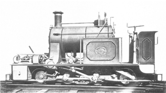
An 1875 advertisement by the Handyside Steep Gradient Co Ltd featured this view as a centrepiece. Note the type of locomotive depicted (? the one used at Avonmouth) and the gripping strutts on the second wagon.
Possibly the most widely publicised engine fitted with the apparatus was the one built by Fox, Walker & Co for the Handyside Steep Gradient Co Ltd which underwent fairly extensive trials on the Cromford & High Peak Railway in Derbyshire. These particular trials were being mooted early in 1876 (per "The Engineer," issue dated 7th April 1876) and for three months in the autumn of that year the loco worked traffic over the Hopton incline. "Engineering" for 13th October 1876 reported on the event, a week after their reporter visited Hopton to view the locomotive at work. "This locomotive .. is a six‑wheeled tank engine with all the wheels coupled and fitted with the winding gear .. at the trailing end. The engine .. has 13 in. cylinders with 20 in. stroke, and the wheels are 3 ft. 6 in. in diameter, while the wheel base is 9 ft. 8˝ in. The winding drum is situated between the frames at the hind end, the rope being paid off from the upper side of the drum, so that, as far as possible, it is kept clear of the ground. Light wooden rollers are, however, provided at intervals between the rails to carry the rope, which is 300 yards long and made of steel wire. The winding drum is driven by a pair of vertical engines with 10 in. cylinders and 9 in. stroke, these engines acting through a compact arrangement of epicycloidal gearing, the arrangement being such that the rope can be paid out without the winding engines being run." Other principal dimensions of the locomotive were: heating surface of tubes, 481 sq ft; heating surface of firebox, 67 sq ft; grate area, 6.9 sq ft; water capacity of saddle tank, 450 gallons; coal capacity, 10 cwt. Average weight in working order was about 22 tons. The braking strutts, arranged on each side of the engine between the leading and driving wheels, were hung by long, almost horizontal links from brackets attached to the frames. These strutts were brought into action by means of a steam cylinder of 10in diameter by 10in stroke; the piston of this was coupled to an arm on a rocking shaft which had cranks to transmit the necessary movement to the strutts. To prevent a shock blow on the rail table when the strutts were applied, the steam ports for the cylinder were arranged for gradual opening only; the bearing springs of the locomotive also tended to absorb any shock. The two cylinders for working the winding drum were positioned vertically, and situated to the rear of the footplate.
On 25th August 1876, "The Engineer" reported that a "locomotive engine, fitted with the patent apparatus manufactured by the Handyside Steep Gradient Company, of Bristol, is now working both passenger and goods traffic for the London and North-Western Railway Company on the Hopton incline of the High Peak Railway, Derbyshire. The gradient on that railway is one in fourteen." One wonders what the Board of Trade had to say with regard to the movement of passengers by this means. Does anyone know what legislation (if any) covered the use of this type of rope haulage with respect to passenger carrying trains in 1876?
The later Handyside standard gauge 0‑6‑0 saddle tank used on the Hop ton incline, as featured in "Engineering" on 13th October 1876.
At the time of these trials on the High Peak line, Hopton incline was normally worked by a stationary winding engine. During its stay the Handyside loco worked traffic from the head of Middleton incline to the top of Hopton incline. When picking up a train at Middleton, it performed any shunting there, and also shunted some quarry sidings en route to the foot of Hopton with its train. The incline at Hopton was ascended in the general manner previously described, though it should be noted that the engine was attached to its train in conventional fashion (by chain link couplings) and was not able to ascend the incline solo without stopping first. (This non‑stop method was that initially advocated by Handyside but in all probability never saw actual use.) Therefore, on arrival at the foot of Hopton the train was stopped, the locomotive uncoupled, and its hauling rope attached to the first vehicle of the train. The loco was now in a position to begin the ascent. During the "Engineering" reporter's visit in October, the locomotive's performance was evaluated by a few simple tests. A load of 20 tons (one loaded wagon of coal and two empties) took about 7˝ minutes on the ascent of Hopton, timed from when the engine started from the foot of the incline to when the load arrived at the top. A load of 37˝ tons (two loaded wagons of coal and a wagon of grain) took a little longer for the same distance, namely about 8 minutes. During both these performances the trains were light enough to be taken up as one load (that is, not divided) and the incline was short enough to be traversed in two lifts. The braking power of the strutts was also successfully demonstrated with a train of ten trucks and a van (75 tons in all) that was taken down the incline. Ordinary brakes on the van and the locomotive were applied but these alone were insufficient: the retardation of the gripping strutts enabled a controlled descent to be made, with several demonstration "dead stops" achieved from a speed of about 6mph. No mention is made of special Handyside wagons being used in the trials so I assume that on the ascent of Hopton the train vehicles were not held stationary by gripping strutts but by ordinary brakes being pinned down whilst the loco went on ahead solo.
An advertisement from "The Engineer" of 11th August 1876, which confirms that the trials on the High Peak Railway started early in August, if not before. It seems as if Handyside took up residence in Wirksworth so that he personally could meet any potential customers!
Following the trials on the High Peak Railway the locomotive returned to Fox Walker's works at Bristol, where it was "the principal object of interest" for a party of members from the Institution of Mechanical Engineers who paid a visit on 24th July 1877.
In his monograph, "The Cromford & High Peak Railway" (Oakwood Press, 1962), A. Rimmer mentions that before 1877 "an attempt had been made to operate the Hopton incline with a special locomotive, built by Messrs. Handysides, Engineers, of Derby." The description that follows leaves no doubt that it was in fact the engine reported by "The Engineer" and "Engineering" during the latter half of 1876. Rimmer makes no mention of Fox, Walker & Co as its builder and seems to have confused Henry Handyside with Andrew Handyside & Co Ltd, bridge builders and iron founders of Britannia Ironworks, Derby. At one time Henry Handyside did live in Derby. Was there any connection between the two?
It is appropriate at this point to pause and discuss the exact identities of the preceding locomotives. Surviving Fox Walker records for the period in question are incomplete, and the first listed Handyside locos are works numbers 314-316. Fox Walker's Locomotive Order Book, in an entry dated 5th October 1875, describes 314 and 315 as "Two 9" cyl. tank locos .. fitted with patent apparatus." The class type has been amended, possibly to HP from M, and the order was for only one loco initially, as against 314 there is a note "altered from 299" and the word "one" has been changed to "two". Society records give 314 as an 0‑4‑0 saddle tank built in 1876, with loin by 14in outside cylinders and 2ft 6in diameter wheels. It is shown in the Fox Walker list as going new to "Wm. Williams, Upper Forest Tinplate Works" at Morriston, Glamorganshire, and is given as a "Handyside's Patent Engine". The auxiliary winding engine had cylinders of 9˝in diameter by 9in stroke. Named MARY BEATRICE, the loco was returned to Peckett in 1892, and resold to James Pain Ltd, Corby Brickworks & Ironstone Pits, Northamptonshire. Existing Peckett Boiler Certificates for 314 confirm that it carried the same name with both these owners. The Williams' certificate, when the boiler was tested on 17th February 1888, quotes the class as M2 but that for 20th December 1892 - by which time it had been fitted with a new circular copper firebox for "James Pain Esq., Corby" - shows it as class HP! Just to confuse matters more, Fox Walker 299 - altered to 314 per Fox Walker records - is shown in Society lists as being an M2 class loco with 9in by 14in cylinders supplied new to Thos. Docwra & Son, London, named TERRIER. (The alteration may have been to the design of Fox Walker 299 and not to the actual locomotive.) Suffice it to say that the weight of 314 would be in the region of 15 tons (or less) so it could well be the "small locomotive" tried at the Atlas Works in March or April of 1876. The Fox Walker list gives the same dimensions for 315 as 314 and also states that 315 was a "Handyside's Patent Engine", but quotes no owner. A note from Society records indicates that it was supplied to "Joseph Tinn, Ashton Rolling Mills, Bristol". The engine used at Avonmouth - the first Handyside loco, per Handyside himself - defies positive identification. In part it would seem to fit the description for Fox Walker 314, as both are described as being altered: the Avonmouth engine from "an engine already partially constructed", and 314 from 299. However, this does not resolve the differing wheel arrangements of the two locomotives. I personally feel that there was a loco fitted with Handyside's apparatus previous to 314. I have been told that at least one of the old employees at the steelworks of Samuel Fox & Co Ltd, Stocksbridge, near Sheffield, maintained that their first No.2 (Fox Walker 284 of 1875) carried a plate stating "Handyside's Patent". Apparently the loco had been fitted with Handyside's Steep Gradient Apparatus, complete with gripping strutts. A photograph of Fox's No.2 shows it externally to be very similar indeed to the engraving of the Avonmouth engine, though it is immediately apparent that when photographed the Apparatus was not carried. Obviously, this does not preclude from it having been removed some time previously. The earlier history of 284 is a little obscure. Fox Walker Order No. 586, dated 16th February 1875, was for two class T 0‑6‑0 saddle tanks with 14in by 20in outside cylinders. One of these, Fox Walker 283 of 1875, went new to the Nunnery Colliery Co Ltd, Sheffield. The other (Fox Walker 284 of 1875), according to the list, was sent to Mersey Docks, Liverpool, on 17th September 1875 for shipment to an unknown customer. It carried the name MARIE ALEXANDROVNA but was never delivered as originally planned, being sold to Samuel Fox & Co Ltd at Stocksbridge. Fox Walker records do not indicate that it was other than a normal locomotive, but could its refusal by the original purchasers - following completion of "trials" at Avonmouth - have been due to the fact that they decided they no longer required a Handyside locomotive? Perhaps Fox, Walker & Co were then obliged to remove the apparatus in order to sell 284 as a conventional locomotive. More substance is added to this argument when one consults the Fox Walker locomotive list. At the time in question the only recorded locos which could be the Avonmouth Handyside are 284 and 285: the other 0‑6‑0 saddle tanks built during this period were all of class B1, and this type had a shorter wheelbase than the Avonmouth loco. It would be of interest to be able to prove this idea but this has not been possible as few dimensions for the class T locomotives survive. Strangely, 284 at Stocksbridge was recorded as having 3ft 0in diameter wheels, not 3ft 6in as on the Avonmouth loco. However, some mis‑recording could have taken place: a rough scaling on the photo of Fox Walker 284 indicates that the wheels were nearer 3ft 6in than 3ft 0in diameter.
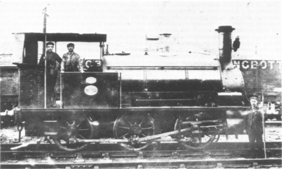
A copy photograph taken from rather a dark view of Fox Walker 284 at Samuel Fox & Co Ltd. Was this locomotive ever fitted with Handyside's apparatus? (collection F. Jones)
Fox Walker 316 of 1876, according to the Locomotive Order Book, was a 13in tank loco of class 131 to order 682, fitted with Handyside's Patent Apparatus. "To be ready in 2 months from April 20th". This entry was dated 25th April 1876, the loco being an 0‑6‑0 saddle tank with 13in by 20in outside cylinders. According to Society records it was sent to Holland for "Vaux & Liege". Are any of our Dutch readers able to amplify this statement - especially with the date of arrival in Holland - or comment on the ultimate fate of the engine? I feel that 316 could well be the engine which was involved in the trials on Hopton incline. The main dimensions of 316 are also those quoted in contemporary reports of the Hopton engine, and the ordering date of 316 fits in nicely with the date of the trials. There is, however, one inconsistency: according to "Engineering" for 13th October 1876 the Hopton engine was "the second locomotive which has been constructed on Mr. Handyside's system". This information would seem to have been provided by Fox, Walker & Co (or the Handyside Steep Gradient Co Ltd) as it also appears in "Iron" for 24th November 1877. But how does the statement fit in with Fox Walker records, for even ignoring any Handyside before 314 it would still make 316 the third such locomotive, not the second. Unless, of course, 314 or 315 was not actually fitted with the apparatus.
For the final episode in the Handyside saga we must turn our attention to its application in military spheres. It has already been shown that ascending inclines by use of Handyside's system was time consuming. Such was the nature of trench warfare that any railway haulage system which worked at all under the conditions met was worthy of consideration, almost irrespective of the time factors involved. Indeed, the principal problem at the War Office was not how long it took to traverse a line once built, but how to build an operational railway before the end of hostilities! Handyside's system, doing away with the need to construct cuttings and embankments, seemed to be a possible solution. "Mining Journal," in its issue dated 26th August 1876, reported that a Royal Engineer Committee on Field Railways was to visit Hopton to witness the experiments there. The Committee must have been suitably impressed, for on 11th May 1878 "Iron" indicated that experiments were "to be carried out at the Royal Arsenal, Woolwich, to test the efficiency of a special kind of locomotive which has been constructed for the new trench railway. This railway is designed to be laid upon the surface of the ground wherever it may be found necessary to construct earthworks or to transport material, the ordinary methods of reducing irregularities by cuttings and embankments being out of the question in field operations. The engine is therefore designed to ascend and descend sharp gradients, and is also fitted with an apparatus for hauling up and lowering down trucks. A hill too steep to be ascended with a load behind may be surmounted by the engine alone, and it may then wind up the load after it. An experimental railway running up and down hill in irregular fashion is being formed near the butts in the Government Marshes adjoining the Royal Arsenal, Woolwich, for the purpose of the trial." Were the above experiments the original motive behind the building of Fox Walker locomotives 399-404 in 1878? These six Handyside trench engines were 1ft 6in gauge 2‑4‑2 "tank" locomotives shown in Fox Walker records as supplied new to the Admiralty at Chatham. Of class HPTE (possibly standing for Handyside Patent Trench Engine?), they had 8in by 9in outside cylinders but the dimensions of the auxiliary engine do not seem to have been recorded. Outside frames were fitted and, possibly because of width limitations, the auxiliary cylinders and winding drum were placed on an extended platform in front of the smokebox. The locomotive, therefore, would presumably be obliged to operate chimney downhill when ascending and descending inclines, thereby creating the undesirable possibility of a dry firebox crown with a low water level. Like their standard gauge counterpart used at Hopton, these locomotives had the gripping strutts placed on each side. Water capacity would have been somewhat limited. Side and saddle tanks were absent from the design and the engines were of such a size that a well or back tank - if either was fitted - would hold but the minimum of water.
An official photograph of one of the rather ungainly-looking trench engines for Chatham Dockyard. The Peckett worksplate is fictitious as the photograph has been "doctored" In existence is an identical (but faded) photograph with the loco carrying a plate lettered "Fox Walker & Co Engineers Handyside's Patent 1878 Bristol" (collection K.P. Plant)
I had originally thought that the loco on trial at Woolwich - assuming it was a Handyside creation - might be the solitary Fox Walker they owned, works number 386 of 1878, a 1ft 6in gauge engine with 5ľin by 6in outside cylinders. However, 386 is shown in Fox Walker records as an 0‑4‑0 tank loco and an official photograph shows it not to have been fitted with Handyside's apparatus when new. It seems highly unlikely that this was fitted to 386 for a short period to cover the Woolwich trials only, so we are led to suppose that the experiments - if they were carried out - utilised one or more of the six Handysides all shown as being delivered new to Chatham. The narrow gauge system serving Chatham Dockyard would seem to have been ideal as a proving ground for these locomotives, with construction of fortifications providing a situation rather similar to the construction of Avonmouth Dock. However it looks as if the original intention was to use one or more of them on the (temporary?) experimental railway at Woolwich. At this stage one cannot help remembering the proposed conversion (to the Handyside system) of one of the 1ft 6in gauge Manning Wardles at Chatham, as already referred to. Did these trials at Woolwich ever take place? If so, was the engine employed a Fox Walker, ultimately destined for Chatham, or a converted Manning Wardle from Chatham? I have been unable to locate anything further on this subject so it is a matter of pure conjecture as to whether the trials were brought to a successful conclusion or not.
The later history and subsequent disposal of the Chatham HPTE locomotives do not seem to be known. Society records indicate that they did not carry names - unlike all their narrow gauge contemporaries at Chatham - and the absence of name and running number would suggest that they were never counted as part of the regular locomotive stock. Could they have been shipped overseas from Chatham?
In presenting Handyside's ideas to the public, the press of the day seems to have been remarkably sympathetic towards them. For example, the gripping strutts caught the eye of several reporters, who seriously advocated their use on the coaches of ordinary passenger trains, to guard against accidents following coupling failures. (It has to be remembered in this context that fail-safe braking of the vacuum type was not commonplace on British railways at this time.) It was also pointed out that the gripping strutts were less destructive than sand, which was normally used as an aid to retardation with conventional brakes on greasy rails. Sand was detrimental to rail table, locomotive tyres and motion alike, whereas the strutts made use of part of the rail not normally subject to wear. The system as a whole seemed to capture the imagination of many; indeed, if one accepted contemporary reports at face value, it seemed to have no bounds as to its potential uses. The most obvious of these was in mountainous areas, where a line worked on the system could be built and operated with the minimum of outlay, especially when compared with a true rack system, a lengthy zig‑zag adhesion line, or a series of inclines worked with costly stationary engines. In its issue for 11th September 1874, "The Engineer" went so far as to explain how judicious placing of strutts, alternative ones working in opposite directions, could be used to enable a train of this type to negotiate a switchback railway without the need for reversal of the train on descending the downhill stretches! Other virtues of the system were neatly summarised in "Iron" for 24th November 1877:-
"By way of comparing the cost of a line to be worked in the ordinary way and on the Handyside system, let it be supposed that an elevation of 38 feet has to be attained. With a uniform gradient of 1 in 80, this would require 120,000 cubic yards for filling, which, at 1s. 6d. per cubic yard, would amount to Ł9600. For working by the Handyside engine, with a gradient of 1 in 10 .. only 16,030 cubic yards of filling would be required, amounting to Ł1200, and thus effecting a saving of Ł8400.
"As tunnels are not only the most expensive works on a line, but also those in which the cost can never be estimated with any degree of certainty, they are only resorted to when no other means are available for overcoming an obstacle. For the same reason it is most important to arrange the tunnel as high up the mountain side as possible, and thus reduce its length to a minimum. By adopting a gradient of 1 in 10 for a short distance on both sides a greater elevation will be obtained, and the length reduced accordingly.
"The fact of a line being constructed on this method in a new country that it may be desirable to open out, does not prevent the gradients from being eased for working by ordinary locomotives, when the traffic shall warrant the additional expense. On the contrary, the work will be so far assisted by the existing line.
"As the steepest gradient on all railways determines the weight of the locomotive required to draw a given load at a required speed up that gradient, so does the weight of the locomotive determine the weight of rails along the whole line. The saving effected in this item is represented approximately by a section of 45 lb. against 75 lb. to the yard. This carries with it lighter chairs, lighter sleepers - now more and more constructed of iron for tropical climates - and less ballast, which frequently has to be conveyed from a distance. The reduction in weight of the permanent-way materials also implies reduced cost of transport to a country which does not produce its own. Another point gained by reducing the weight of the engines is the saving of the wear and tear of the rails, and consequent renewals, which constitute one of the heaviest items in the maintenance of a line. Light rails also wear longer in proportion than heavier rails, for the simple reason that extra weight and strength do not improve the quality of the iron, and that the power of the metal to resist compression remains the same whether in a light or heavy rail.
"Though this system cannot be applied with advantage to existing lines, where the gradients are either too steep or not steep enough, it deserves the careful consideration of those who propose to take a line through mineral districts, which are usually broken and irregular. For contractors, especially, who have to construct temporary lines for conveying materials, and also in military operations, when a line has frequently to be made with the utmost expedition, this system merits earnest attention.
"The cost of hauling a given train will, of course, be greater over a steep gradient than over an easier ascent; but, if an equal height is to be attained in each case, there is a resistance of fewer foot-pounds to be overcome in the case of the steep gradient than in the longer and easier grade. In the Handyside system the line may, in a mountainous country, be reduced by 300 per cent. in length, which, in a sparsely inhabited country is often, owing to the mere question of first cost, the turning point as to whether there shall be a railway or no railway."
It is perhaps as well that Handyside, as Managing Director of the Handyside Steep Gradient Co Ltd, did not live long enough to witness the final rejection of a system which had promised so much following its initial enthusiastic reception by the technical press of the day. He appears to have been quite a prolific inventor of gadgets related to railway matters. Two of his other ideas are worthy of attention. The first concerned the manner in which vehicles in a train were coupled together, and was covered by Patent No. 2323, sealed on 29th December 1874. Handyside proposed that each vehicle should have a continuous metal bar joining the two couplings, so that all the hauling strain remained on the couplings and was not transmitted through the underframe of the vehicle. Such a coupling bar did away with the need for heavy (and expensive) underframing. His other idea was specifically aimed at passenger carrying vehicles, as he was of the opinion that violent side oscillations encountered on fast trains were caused by the wheels striking irregularities in the gauge of the line. To dampen these side blows on the wheels, and prevent them from being transmitted to the body of the vehicle, it was proposed to place shock-absorbing coiled springs on the axles of the vehicles, between the wheel-boss and axle-box. This idea was covered by Patent No.4124, sealed on 12th June 1874.
Peckett & Sons Ltd, the successors of Fox, Walker & Co, seem to have retained something of a soft spot for the Handyside design long after its passing. A framed drawing representing a Handyside loco - probably the Hopton one - at one time occupied a prominent position on the mantlepiece in their Works Office, and up to at least the early 1930's a model of the Hopton locomotive was also kept there! What became of them I wonder?
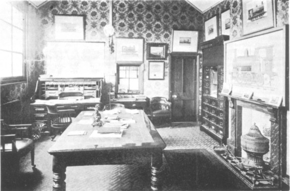
View of the interior of Peckett's Works Office. The Handyside drawing is the large one directly over the mantlepiece on the right of the photograph. (IRS Collection)
In conclusion I wish to thank Messrs D. Clayton, K.P. Plant, R.E. West, R.A. Wheeler and W.K. Williams; also Bristol Public Libraries. All readily provided material or assistance which has helped in the compilation of this article. Special thanks must go to Bill Williams, for his continued patience when answering my persistent queries regarding the Fox Walker locomotive list; also Doug Clayton, whose constructive suggestions and considerable efforts on my behalf have assisted greatly.
The first railway in New Zealand was located on the South Island in Nelson province. Opened on 3rd February 1862, the 3ft gauge Dun Mountain Railway was a short lived venture serving copper mines. With 13˝ miles of tortuous gradients, including 9 miles at 1 in 20, it was worked by horses and gravity. Is this where Handyside's ideas germinated?
The other four initial shareholders were: W.F. Bath, H.L. Jones, H. Handyside and J.F. Havenfield.
Mr James Brunlees was the Civil Engineer responsible for the construction of Avonmouth Docks. He was knighted in 1886 in recognition of his work on the Mersey Tunnel Railway.
'The partial failure of the military railways hitherto made was to be found in the impossibility of executing the works of which ordinary railways consisted, such as cuttings, embankments and masonry, with the rapidity necessary for laying down a field railway at the commencement or even in the early part of a war. [In considering other methods of construction] the Royal Engineer Committee at Chatham had carried out a series of experiments at the camp at Aldershot, of which Captain Luard, R.E., and the writer of the paper had charge. The experimental railway consisted of a succession of timber viaducts, which supplied the place of earthworks, culverts and bridges - and which, when the materials had been prepared, could be erected with great rapidity. The conditions the Committee desired to have fulfilled in the trials were that an engine not exceeding six tons in weight should take a train of 30 tons up an incline of 1 in 50, and travel at an average speed of 10 miles and maximum of 20 miles an hour....
'The experimental railway was one mile in length, the gauge 18 inches, steepest gradient 1 in 50, the sharpest curve 3 chains radius, and one of the viaducts was 660 feet in length and 24 feet in height. The structure was of a simple form, and consisted of two beams which were bolted to a kind of trestlework supports, which were sunk to a depth of 12 inches, and firmly fixed in the ground. The rails being laid on the beams completed the railway, for the construction of which no other than military labour was required. The experiments occupied at intervals a period of twelve months.... [The trials indicated] that a single line of railway could be made over ground similar to that at Aldershot at the rate of two miles a day by 500 men; and that it would be possible to construct a field railway at the speed at which an army of 100,000 men could march. The cost of the mile of railway at Aldershot with sidings, stations, and rolling stock, was Ł3,500....' (From a report in "Iron"; issue dated 16th September 1876, of the paper read by Mr J.B. Fell to the British Association meeting in Glasgow on Friday, 8th September 1876. - KPP)
"In the standard contractors' engines of this firm [Fox, Walker & Co] , all the rods and levers are brought to the footplate as in main-line engines, and have entirely cylindrical boilers so that they can be adapted to a very narrow gauge. They have a neat arrangement of sand-box, which, looked at sideways, forms a continuation of line from the smoke-box to the cylinders." ("lron" 4th August 1877. - TJL)
'WEST SOMERSET MINERAL RY. - The Board of this Railway has been reconstructed, and every effort is being made to re‑open the iron ore mines in the district and to open the Railway as a Light Railway of standard gauge.' ("The Locomotive Magazine," 15th January 1918. As Roger Sellick recounts in his book, "The West Somerset Mineral Railway" (David & Charles 1962), the line was not reopened, an Act for its abandonment being passed on 2nd August 1925. - TJL)
![]()
![]()
![]()
![]()