| THE INDUSTRIAL RAILWAY RECORD |
© SEPTEMBER 1967 |
STATESIDE SWITCHERS
(3) A BALDWIN 2-4-4-2 MALLET
The Mallet type of locomotive was introduced to meet a growing demand for a locomotive having exceptionally high tractive effort, combined with the ability to readily traverse sharp curves. In order to develop high tractive effort, great adhesion weight, and consequently a comparatively large number of driving wheels, are necessary. If, however, more than five pairs of such wheels need to be used, it may not be practicable to couple them all in one group, as the rigid wheelbase becomes excessively long, and the reciprocating parts of unwieldy size, owing to the large amount of power which must be transmitted through them. When, therefore, six or more pairs of driving wheels are required, it is necessary to divide them into at least two groups. Various ways of doing this have been tried; but that devised by Anatole Mallet, a French engineer, and first used by him in Europe in 1889, was found to be the most practical design for the high-capacity locomotives required by American railways.
The Mallet employs a single boiler, which is placed over two groups of driving wheels, each group having its own frames, cylinders and motion. The frames of the rear group are held in rigid alignment with the boiler, while those of the front group are hinged to the rear frames by means of a pin placed on the centre line of the locomotive. The front frames support the forward end of the boiler through sliding bearings, known as waist bearers. When the locomotive enters a curve, the front frames swing about the hinge-pin as a centre, the movement being comparable to that of a radial truck. The front boiler bearing is fitted with controlling springs, which tend to hold the front and rear frames in alignment with each other. These springs assist the rear unit in following the front unit into a curve, and they also aid in restoring the alignment of the front and rear units after the curve has been traversed.
The lower section of each of the waist bearers is fitted with a brass plate, on which the upper section of the bearer slides. This sliding surface is lubricated, and the brass plate takes the wear. The front waist bearer is fitted with clamps, for the purpose of preventing the frames from dropping away in case of derailment, or if it is necessary to handle the assembled boiler and frames with a crane.
The cylinders are arranged on the compound system. Those that drive the rear group of wheels receive steam direct from the boiler and act as the high pressure, while the front cylinders receive the high pressure exhaust, and thus act as tae low pressure. Their exhaust, in turn, is discharged up the chimney to create a draught for the fire. The ratio of the cylinder volumes is usually between 2.35 and 2.50. The receiver pipe connecting the high and low pressure cylinders, and the exhaust pipe connecting the low pressure cylinders and smokebox, are fitted with flexible joints so that they can accommodate themselves to the swing of the front frames. These pipes, however, carry steam at moderate pressures only; hence less difficulty is experienced in keeping the joints tight than in the case of some other articulated designs.
Whenever possible, the Mallet is designed so that the centre line of the ball-joint at the back end of the receiver pipe coincides with the hinge-pin centre, so that the pipe at all times is parallel with the front frames. A slip joint is placed near the front end of the pipe to allow for expansion and contraction. Both joints are fitted with packed glands, so that they can be kept tight and wear can be taken up. The slip-joint in the exhaust pipe is not provided with a gland, but it has a long sliding fit, and water grooves and snap rings are used to prevent leakage. The ball-joint at the rear end of this pipe is kept tight be means of a coiled spring, which holds the pipe flange firmly in its seat.
The use of superheated steam in Mallet locomotives, especially of the larger sizes, is practically universal. The superheater itself is arranged as in a single expansion locomotive; but in a Mallet, the high pressure steam pipes must necessarily extend back from the superheater header in the smokebox, to the high pressure cylinders. Here the distribution is controlled by piston valves. Either piston or balanced slide valves, the latter preferably double-ported, may be used on the low pressure cylinders. A satisfactory method of lubrication is to run one lubricator connection to each high pressure steam chest, and one to the receiver pipe leading to the low pressure cylinders. Emergency lubricators are frequently applied to the latter cylinders, but ordinarily their use is not necessary.
It is necessary on a Mallet locomotive, to control two sets of valve motion simultaneously, and to do this a power reverse mechanism is normally required. Such mechanism is often operated by compressed air from the Westinghouse brake pump, though steam operation is also used.
The articulated joint, connecting the front and rear frames, is designed to provide flexibility in a vertical as well as a horizontal plane. Thus, when the locomotive passes over uneven tracks or sudden changes of grade, the frames can have a vertical movement relative to each other.
In order that the locomotive can develop full power when starting a train, a valve is usually fitted which permits high pressure steam to enter the low-pressure cylinders direct from the boiler. On Baldwin locomotives, and possibly others too, this valve may be automatic though normally it is manually operated. The automatic version is designed to cut off the supply of steam from the boiler as soon as the pressure in the receiver pipe reaches a pre-determined value. A later refinement fitted to many locomotives was a system of intercepting and reducing valves, which permitted the entire locomotive to be worked "single-expansion" – a useful feature when hauling heavy loads up steep inclines.
Although never used in Britain, the Mallet articulated locomotive could be found in large numbers in almost every European country. Even today, those French public narrow gauge railways with steam locomotives have Mallets, and a small number are still to be found here and there in industrial service. It was 1904 before the type became commonly used in America, in which year the Baltimore & Ohio Railroad introduced 0-6-6-0 locos on a 17 mile climb in West Virginia. Experiences here showed that it was desirable to have a front pony truck to guide the loco around curves, and future American Mallets incorporated this and other improvements. By 1909 the design had become popular, and in that year the Little River Railroad, a 14 mile long timber line in the Great Smoky Mountains, ordered a Mallet.
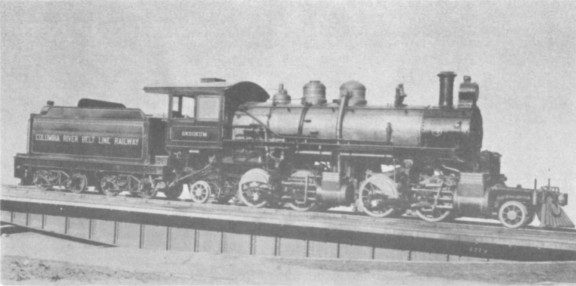
SKOOKUM in 1910 - Official Baldwin Works photograph, by
courtesy
of H.L. Broadbelt.
The Baldwin Locomotive Works at Philadelphia designed the loco to haul 200 ton trains around 160ft radius curves and up 1 in 40 inclines, the axle loading being limited by the 56lb rail in use on the line. The length over the buffer beams was 60ft 10in, height to top of chimney 14ft 0in, the total weight of the loco being 53 tons and the tender a further 36 tons in working order. With 4ft 0in drivers and 2ft 4in pony wheels, the tractive effort was 27,430lbs. Cylinder stroke was 22in, the rear (live steam) cylinders being 15in diameter, whilst the front (exhaust steam) cylinders were 23in diameter. Due to the effort required to shift the four sets of Walschaerts valve gear, a power reverser was fitted. Traction was assisted by an adequate supply of sand boxes – two rectangular ones on the bufferbeam for the front engine, and a sand dome on the boiler top for the rear engine – and the passage of sharp curves was assisted by flange oilers.
Theoretically, the use of steam twice over gave the Mallet greater efficiency than a conventional locomotive, but this was not without its price. If either engine slipped, the steam pressure to the other immediately became greater, thus causing the other engine to slip also, each engine tending to trip the other into instability. In later years, when better methods were developed for getting high-pressure steam through the jointed pipes without leakage, the Mallet generally gave way to simpler articulated designs.
When Baldwin delivered the loco to Little River they numbered it 126, although it was only their third locomotive. After a few trial runs, however, 126 was returned to the Makers as unsuitable for the line, due to derailments taking place on the curves. Baldwin then built a slightly smaller version, with reduced driving wheel size and other detail modifications; Little River accepted this one and numbered it 148. Following this success, Baldwin built many more similar machines for timber lines – one, with even smaller driving wheels, became number 64 on the 23 mile long Laurel & Tallahoma Western Railway in Mississippi, which was owned by Eastman, Gardiner & Co.
Baldwin were not left with 126 on their hands for long for in the following year, 1910, it was converted to an oil-burner, de-numbered, named SKOOKUM, and sold to the Columbia River Belt Line Railway, another timber line north of Astoria in Washington. Here the locomotive performed very satisfactorily, being kept until the area had been denuded of trees. The Carlisle Lumber Co., of Onalaska, Washington, were the next owners, and here the name SKOOKUM was removed and replaced with the number 7. In due course the Carlisle Co. sold 7 to the Mud Bay Logging Co., near Olympia, but here the locomotive did not perform as well as they expected, and it was sold again, this time to the Deep River Logging Co., who had a 20 mile line near Deep River, Washington. In 1953, 7 was still working satisfactorily, but shortly afterwards the area became worked out, and during the last few days of operation the Mallet toppled off the track on one of the curves, coming to rest on its side at the foot of a low embankment.
After final closure of the line, the track was removed for scrap, but the Mallet was left lying where it had fallen, and the next generation's growth of timber sprang up all around. In 1960, however, Mr.Charles G. Morrow arranged for it to be transferred to a railroad museum near Seattle, it being necessary to dismantle the locomotive for transportation. (Information on the present status and whereabouts of this Baldwin would be welcomed. – Hon. Eds.)
The drawings of J. Harold Geissel, copyright 1962, are reprinted by special permission of MODEL RAILROADER magazine, Milwaukee, U.S.A.
![]()
PUBLICATION REVIEW
LIGHT RAILWAYS OF THE FIRST WORLD WAR, by W.J.K. Davies – 196 pages, 58 photographs. (David & Charles, 35/-)
All users of the Club's Pocket Books will be acquainted with the footnote "ex WDLR" applicable to many vintage locomotives, and the full story behind these initials may now be read in this excellent book. Despite chaotic beginnings largely caused by an anti-rail faction in the British High Command, the book relates how the extensive light railway systems were established and expanded in the various theatres of War, being operated with full traffic control and a form of block working. Details are given of some 750 steam locomotives – from the ubiquitous Baldwins to the mysterious Barclays – and of the internal combustion tractors which numbered well over 1,000; examples of almost all WDLR types of loco subsequently saw service on British industrial lines. The tracks were, of course, of a temporary nature, and it comes as a surprise to read that an extensive part of the French system remained in use until the 1950's. It is perhaps a pity that the drawings of the locomotives and rolling stock are not of a quality in keeping with the remainder of the book, but the well-chosen photographs which illustrate all aspects of the subject adequately compensate for this short-coming. This book is an essential addition to the library of every Light Railway, Industrial and Narrow Gauge enthusiast.
![]()
![]()
![]()
![]()