| THE INDUSTRIAL RAILWAY RECORD |
© DECEMBER 1966 |
TRACTION ENGINES AS LOCOMOTIVES
(2) STEAM SAPPER No. 5
JOHN P. MULLETT
As is well known, the firm of Aveling & Porter bad its beginnings in the 1850’s when Thomas Aveling converted a number of portable steam engines, owned by friends in the Canterbury district, to self moving engines by means of a chain drive. In 1860 he had begun making traction engines proper at his Rochester works, Kent, and these too were driven by means of a pitch-chain, During the 1860’s he began a series of tramway locomotives using the same method of drive and a late example - no.807 of 1872 - happily survives today in the Clapham Museum.
However, in the year 1870 Aveling exhibited at the Royal Show, Oxford, a neat little engine of 5 nominal horsepower which had gear drive instead of chain. It embodied his patent of extending the sides of the firebox upwards and backwards to form hornplates which carried the crankshaft, countershaft and driving axle. This was in place of the method then generally used of bolting or riveting brackets of cast or wrought iron to the firebox. In response to the request of a Government Committee, Aveling had also considered the traction engine for military purposes and in 1868 had produced his chain driven STEAM SAPPER No.1. He now embarked on a series of smaller and lighter gear driven engines which were specially constructed to ensure safe passage over pontoon bridges; the weight did not exceed the 95 cwts. of the heaviest siege gun of that time, the Armstrong Breech-loader. The first was STEAM SAPPER No.2 in 1871.
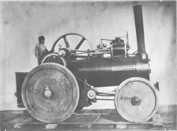
STEAM SAPPER No.5, however, seems to have been something of an exception. It was no. 830 of 1872 for the School of Military Engineering at Brompton (now known as Old Brompton), Gillingham, Kent, and from our illustration it appears to have been supplied as a convertible road to rail locomotive. The flywheel was 4' 6" in diameter, and the axles - 6' 4" long with a diameter of 4⅜" - were fitted with compensating gear and gunmetal axleboxes on both sides. The winding cone was keyed to the crankshaft which had a diameter of 2⅞". Double steam domes were fitted, and the wrought iron chimney had a cast iron base.
This little engine, of 6 nominal horsepower, in common with most others of its class, was fitted with a single road speed and was put in or out of gear by sliding a pinion along the crankshaft and holding it in the required position by means of a leather strap buckled round the shaft. In its rail form a wooden beam seems to be inserted longitudinally beneath the boiler and ending in a simple buffer - and in our illustration the steering gear still seems to be connected! It should perhaps be mentioned that in the case of the engine at the Oxford Show a patent slip eccentric was used and link motion dispensed with, but in those examples the writer has been lucky enough to see - including the one preserved in the Science Museum at South Kensington and STEAM SAPPER No.5 - conventional link motion was used. The four slide bars, big ball governors, short smokebox and Salter safety valves are all very typical of the Aveling of this period.
Messrs. Aveling-Barford Ltd., who have very kindly checked their records for me, seem unaware that any "Steam Sappers" were built other than as road machines, and it would be interesting to know why this one was so turned out.
![]()
![]()
![]()
![]()
![]()
![]()
![]()